TOPOLOGY
LANs are classified depending in the topology, access method, signalling method, transmission medium and
transmission mode.
The control of the network is of two types, viz. centralized and distributed. With centralized
control, access to the network and allocation of the channel is controlled by one node, such as a dedicated
communications processor or switch. When control is distributed, nodes have ability to establish connection
and access the network channel independently, according to an accepted set of rules.
Most LANs are based on simple structured topologies, like the RING, BUS or STAR, Some of the basic
characteristrics of these topologies are outline as follows:
Hierarchical Topology:
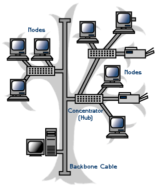
A Hierarchical topology connect multiple star networks to other star networks. This types of topology
contain a central root node that is top-level hierarchy which is connected to one level lower in hierarchy.
It maintain a point-to-point link at the end of the pervious level node. The total number of point-to-point
link in a network based on the physical hierarchical Topology.
 Nodes setting in
hierarchical Topology
- Advantages
- It support point-to-point connection and wiring for individual segments.
- Stystem access imediate and larger networks.
- It supported by several hardware and software vendors. Disadvantages
- The whole network depends on the types of cable.
- It depends on the root trunk whoch is backbone of the network.
- If a root network fails, the entire network will fail.
- It is difficult to configure.
- This topology will have at least three hierarchies in the hierarchy network, all based on the roor node(below figure)
- It support two networks, the star and the linear topology, which connect the nodes.
- Nodes can be added at any level of hierarchy.
- The higher level in the hierarchy performs more functions than the lower level.
Features

Fig. Hierarchical Topology
Bus Topology:
Bus topologies are multipoint electrical circuits that can be implemented using coaxial cable, Unshielded Twisted Pair (UTP) or Shielded Twisted Pair (STP). Data transmission is bidirectional, with the attached devices transmitting in both directions. While generally operating at a raw data rate of 10 Mbps, actual throughput is much less. This is employed frequently in the LANS with distributed control in all nodes, as shown in Figure 3, share the common bus. Messages placed on the bus are transmitted to all nodes. Nodes must be able to recognize their own address in order to receive messages. However, unlike nodes in a ring, they do not have to repeat and forward messages intended for other nodes. As a result, there is no delay and overhead associated with retransmitting messages at each intervening node. Because of the passive role node play in transmission on the bus, network operation will continue in the eventof node failures. This makes distributed BUS network's inherently resistive to single point failures.
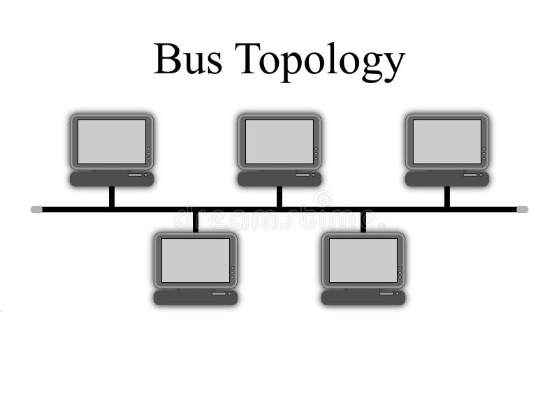
Fig. BUS Topology
Bus networks employ a decentralized method of media access control known as CSMA (Carrier Sense Multiple Access), that allows the attached devices to make independent decisions relative to media access and initiation of transmission. This approach results in data collisions and requires frequent retransmission. Bus networks are specified in the IEEE 802.3 standard, and generally have a maximum specified length of 1.5 miles (2.5 Km). Ethernet is based on a bus topology. A tree topology is a variation on the bus topology, with multiple branches off the trunk of the central bus. Bus networks also suffer from the vulnerability of the bus, as if, one node is down, all nodes in the bus will be down. Similarly, tree networks are dependent on the integrity of the root bus.
Examples of Bus Topology
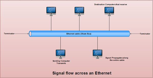
Ethernet: The best alternative high-speed and cost effective LAN called Ethernet. Data
transmitted and received at rate of million bits second. Heavy coaxial cable (thick net) fibre optic cable
are used closets. Thick net coaxial used medium long distances where level reliability needed medium. At
upper cost, the fibre higher reliability and beyond. light duty coaxial cable known thin net normally used
connect workstations within the same room. These mirror bigger picture of workstations in laboratory
surroundings. Figure shows Ethernet where sender transmits modulated carrier wave that propagates from
sender towards both ends of cable.
Ethernet was first designed and installed by Xerox Corporation at Palo Atto Research Center (PARC) in mid-1970. In year 1980, DEC Intel and Xerox came out with joint specification which has become the facto standard. Ethernet named DIX from this period onwards. gained this name after business sponsors Digital, Intel and Xerox.
Star Topology The distinguishing feature star topology that nodes are joined at single point, as shown in Figure This single point called as central node, hub, switch, which other devices are attached directly, generally via UTP or STP. This topology frequently used networks which control the network located in central node. This method optimal when the bulk of communication between the central and outlying nodes. traffic high between outlying nodes, undue switching burden placed on central node.
Transmission rates vary with AT&T's Star LAN operating system at 1 to 10 Mbps, and both 100 Base-T and 100VG-AnyLAN at 100 Mbps. The primary advantage of a star is that a disruptive or failed station can be isolated, thereby eliminating any negative effect it may have on LAN performance. Additionally, each node has access to the full bandwidth of the LAN, at least in a LAN switch environment. The primary disadvantage is that a hub failure is catastrophic as all connectivity is provided through the central hub, its failure affects the entire LAN.

Example of Star Network Asynchronous Transmission Mode (ATM): Asynchronous Transfer Mode (ATM)is International Telecommunication Union-Telecommunication an Standardization Sector (ITU-T) is a standard for cell relay. Here, information about video, data, or voice and other service types is communicated in tiny, fixed-size cells. Networks of ATM's are connection-oriented. In communication, ATM has emerged as a standard. It provides medium to high bandwidth and a virtual link between the delivery of real-time data, video and voice. Separate networks carry data, video and voice information because these traffic types have diverse traits. For example, data traffic is likely to be 'bursty'. It means that data traffic need not communicated for a long time and whenever it does, large amounts of information is communicated instantly.
Video and voice are sensitive to when and in what order the information arrives in one hand and on the other hand, it is likely to be even in the quantity of information needed. Seperate networks are not needed with ATM's. It is a standards-based technology designed to contain the transmission of voice, video and data, all at the same time.
Information needed to be delivered is segmented into fixed length calls and then transported and reassembles ones it reaches its destination. The length of the ATM is fixed at 53 bytes. This allows the information to travel in an expected manner, thus, holding various types of traffic on the same network. The cell is divided into the header (5 bytes) and the payload (48 bytes). The payload carries the authentic information, i.e., data, video or voice, while the header addresses the mechanism.
Ring Topology
The ring architecture is a distributed architecture, with minimal connectivity and a topology of two links
connected to every node as shown in Figure 6 and forms unbroken circular configuration. Figure 6 shows a
network laid out in a physical ring or closed loop, configuration. Transmitted messages travel from node to
node around the ring. Each node must be able to recognize its own address in order to accept messages.
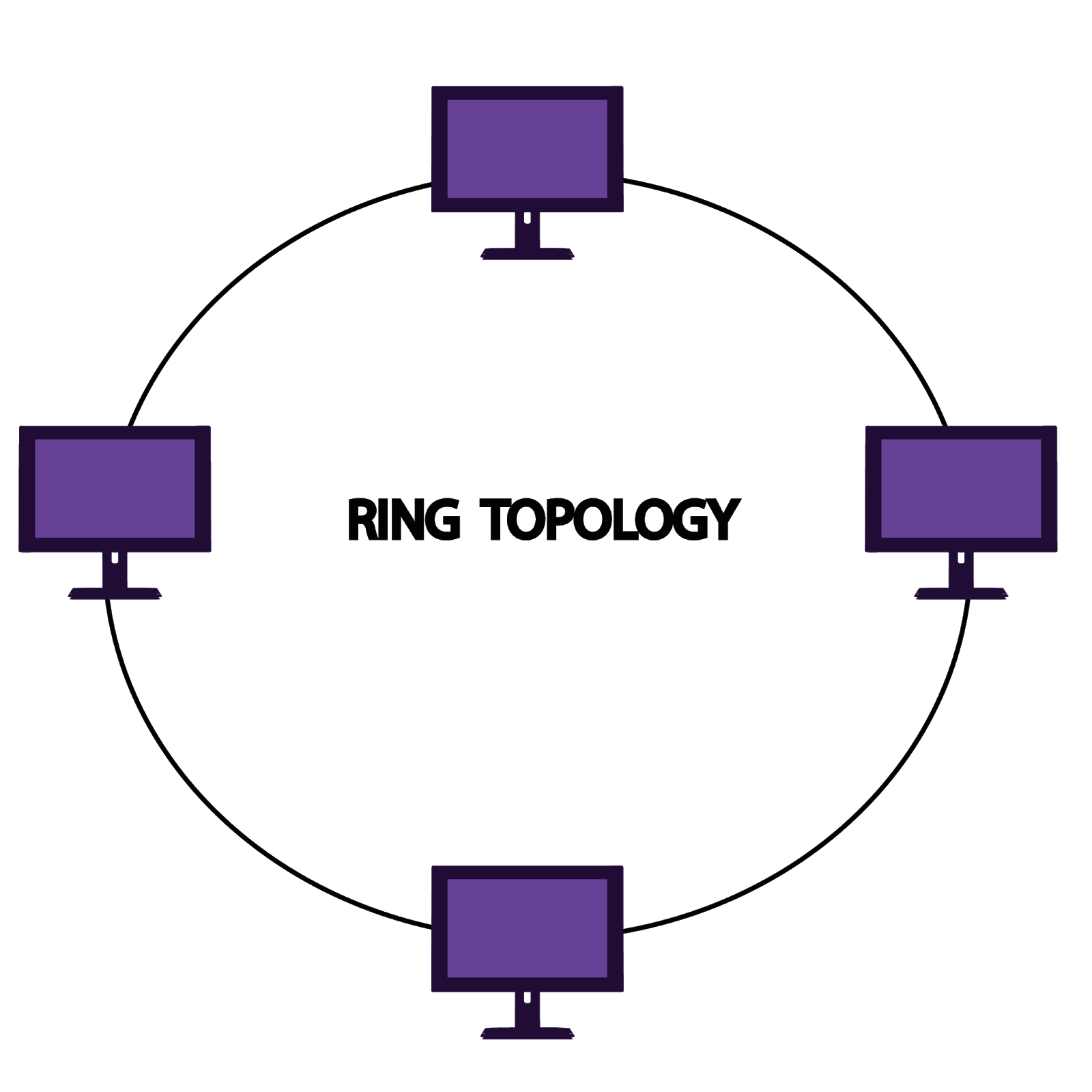
Information travels around the ring in only one direction, with each attached station or node serving as a
repeater. Rings generally are coaxial cable or fibre in nature, operating at raw transmission rates of 4,
16, 20 or 100 Mbps or more. Rings are deterministic in nature, employing token passing as the method of
media access control to ensure the ability of all nodes to access the network within a predetermined time
interval.
Ring networks with centralized control are known as loops. When networks with distributed control are
used, some form of control strategies must used to avoid conflicting demands for the shared channel. The
popular strategies are token passing, circulating slot, register techniques.
Priority access recognized. A master control station responsible controlling access to transmission medium. Backup control stations responsibility in the event of failure of the Throughput is very close bandwidth, as data collisions do not occur in such carefully controlled environment. On the negative side, the failure of single node compromise entire network. Ring networks are specified in the IEEE 802.5 standard. Passing Ring, IBM Token Ring and FDDI all are based on ring
Example of Ring topology
Token Ring: IBM Token Ring specifies a local area network access and
topology. In IBM
token ring topology, computers or stations are attached to the bus in ring structure and uses broadcast
token supervisory frame to obtain access to communication channel. The computer or node wants transmit data
must obtain circulating token before doing so. When node finishes transmission, the token released to the
next node in the ring. this manner the token is passed from one node to another node to provide a chance to
each node transmit.
operates at 16 Mbps and can be used computers from computers from other vendors and devices, such printers.
The published standard as IEEE 802.5 for token ring in 1984 after IBM Token specifications. Therefore, most
of the IEEE specifications are similar to completely compatible with IBM Token Ring network. The objective
of token is provide reliability at functional levels of LAN. topology intends address features systematic
wiring, configuration, maintenance, fault tolerance redundancy.
Fiber Distributed Interface (FDDI): FDDI developed as reliable high-speed network to voluminous traffic. provides data speed at rate 100Mbps and capable supporting stations on a network. operates on fibre through transmission of light pulses conveying information back and forth between nodes. In some case, it may copper using electrical signals. A related technology, Copper Distributed Interface (CDDI) works like FDDI using copper cables instead of fibre cables.
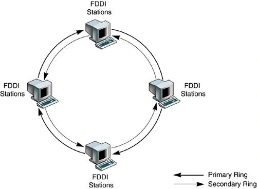
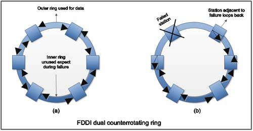
FDDI is able to maintain high reliability because of the provision of two counter-rotating rings as shown in below Figure. in FDDI networks. These provide a backup to each other by providing an alternate way to get the data, it something goes wrong on the network. Figure 7(b) illustrates the data flow when one station fails. When a node fails, the adjoining node uses the reverse path to form a closed ring. FDDI provides reliability because of its ability to fix its own problems
Mesh Topology In a mesh network, each pair of nodes is connected by means of an exclusive point-to-point link. Each node requires a separate interface to connect with the other device. Mesh networks are seldom constructed in practice. They are useful in situations, where one node or station frequently sends messages to all other nodes. Otherwise, a considerable amount of network bandwidth is wasted. The advantages are excessive amount of bandwidth and inherent fault tolerance. The structure of a mesh network is shown in Figure
